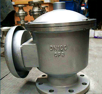
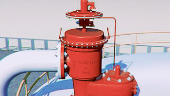
Sometimes referred to as pressure and vacuum relief valve, the breather valve is an important part for atmospheric tanks & vessels in which solvents are filled and drawn at a high flow rate. This type of valve is installed in the in-and out-breathing lines of tanks, vessels and process equipment to retain toxic vapors and avoid atmospheric contamination, thus balancing unpredicted fluctuations in pressure & vacuum and providing increased fire protection and safety.

The internal structure of the breathing valve is essentially composed of an in-breathing valve and the out-breathing valve, which can be arranged side by side or overlapped. When the tank pressure is equal to atmospheric pressure, the disc of the pressure valve and the vacuum valve and the seat work together closely because of the “adsorption” effect, making the seat tight without leakage. When the pressure or vacuum increases, the disc opens and retains a good seal because of the “adsorption” effect on the side of the seat.
When the pressure in the tank rises to the design values allowable, the pressure valve is opened and the gas in the tank is discharged into the outside atmosphere through the side of the vent valve (namely the pressure valve). At this time, the vacuum valve is closed due to the positive pressure in the tank. Conversely, the out-breathing process takes place when the tank is loaded and evaporation of liquid due to higher atmosphere temperature, the vacuum valve opens due to the positive pressure of atmospheric pressure, and the external gas enters the tank through the suction valve (namely the vacuum valve), at this point the pressure valve closes. The pressure valve and the vacuum valve cannot be opening at any time. When the pressure or vacuum in the tank drops to normal, the pressure and vacuum valves close and stop the process of exhaling or inhaling.
The breathing valve shall be sealed under normal conditions only if:
(1) When the tank is bleeding, the breathing valve begins to inhale air or nitrogen into the tank.
(2) When filling the tank, the breathing valve begins to push the exhaled gas out of the tank.
(3) Due to climate change and other reasons, the material vapor pressure in the tank increases or decreases, and the breathing valve exhales the vapor or breathes in air or nitrogen (usually called thermal effect).
(4) The tank’s liquid evaporates sharply due to the heated exhaled gas in case of fire, and the respiration valve starts to deflate out of the tank to avoid the damage of the tank due to overpressure.
(5) The working conditions such as pressurized transportation of volatile liquid, chemical reactions of internal and external heat transfer devices, and operational errors, the respiration valve is operated to avoid damage to the storage tank due to overpressure or super-vacuum.
DIN EN 14595-2016– Tank for the transport of dangerous goods-service equipment for tanks-pressure and vacuum breather vent.

(1) the breather valve shall be installed at the highest point on the top of the tank. Theoretically speaking, from the perspective of reducing evaporation losses and other exhausts, the breather valve should be installed at the highest point of tank space to provide the most direct and maximum access to the breather valve.
(2) The large volume of tanks to prevent a single breath valve because of the risk of failure overpressure or negative pressure can be installed two breathing valves. To avoid two breathing valve operation and increase the risk of failure at the same time, usually the two breathing valve suction and discharge pressure in gradient type design, a working normally, the other is spare.
(3) If a large breathing volume causes the breathing volume of a single breathing valve to be unable to meet the requirements, two or more breathing valves can be equipped, and the distance between them and the center of the tank top should be equal, that is, symmetrical arrangement on the tank top.
(4) If the breathing valve is installed on the nitrogen blanketing tank, the connecting position of the nitrogen supply pipe must be far away from the breathing valve interface and inserted into the storage tank by the top of the tank for about 200mm, so that the nitrogen does not discharge directly after entering the tank and plays the role of nitrogen blanketing.
(5) If there is an arrestor in the breathing valve, the influence of the pressure drop of the arrestor on the discharge pressure of the breathing valve must be considered to avoid overpressure of the tank.
(6) When the average temperature of the tank is lower than or equal to 0, the breather valve must have anti-freezing measures to prevent the tank from freezing or blocking the valve disc caused by the tank’s poor exhaust or insufficient air supply, resulting in the tank overpressure drum tank or low pressure deflated tank.
Forwarded from Perfect Valve
Contact: Ivy Yu
Phone: 86-13757734757
Tel: 86-577-67962253
Email: info@dorytestbench.com
Add: Heyu Industrial Zone,Dongcheng,Yongjia,Zhejiang,China